AirPods Max Headband Connector Replacement
Table of Contents
#
Introduction
This seems to be a common issue with the AirPods Max (lightning). This repair is done on the lightning version. I haven’t looked too closely into the revised product, but it’s likely to be the same design.
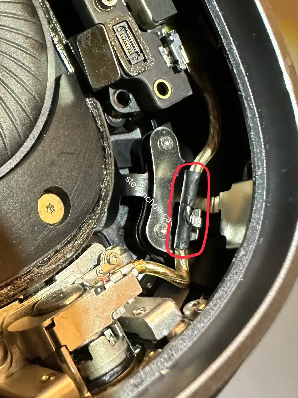
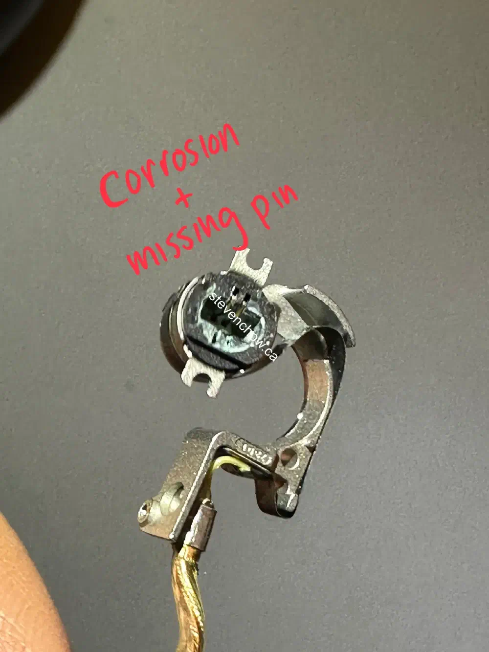
This area can be damaged in two ways:
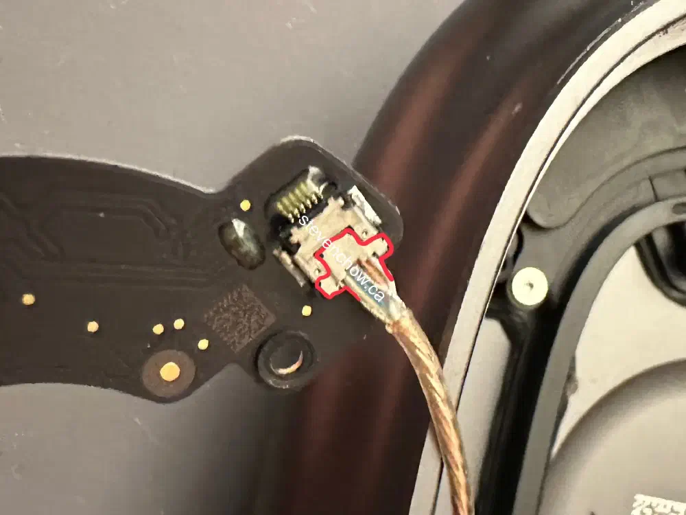
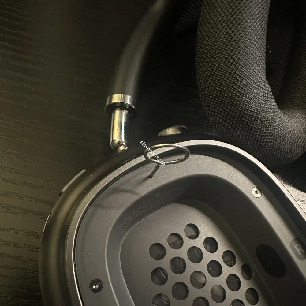
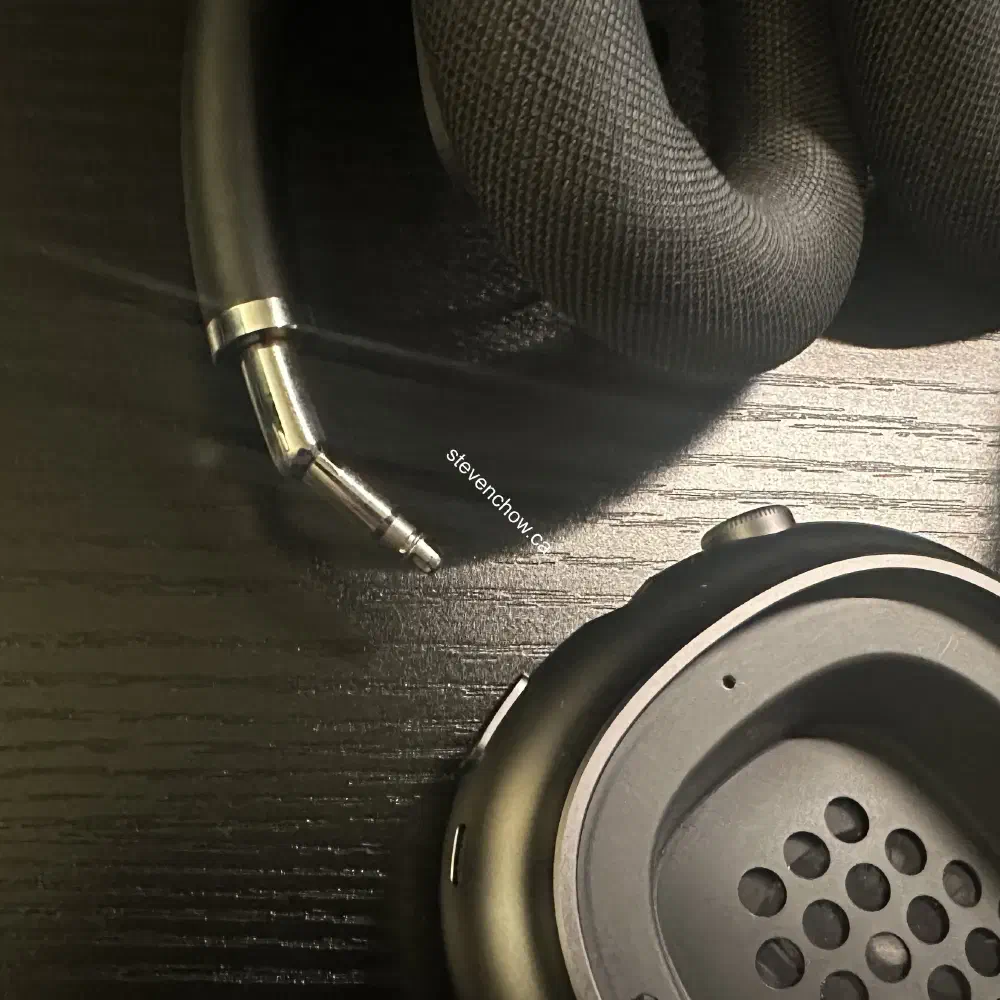
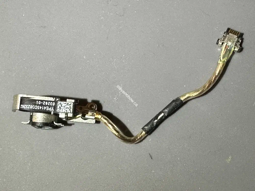
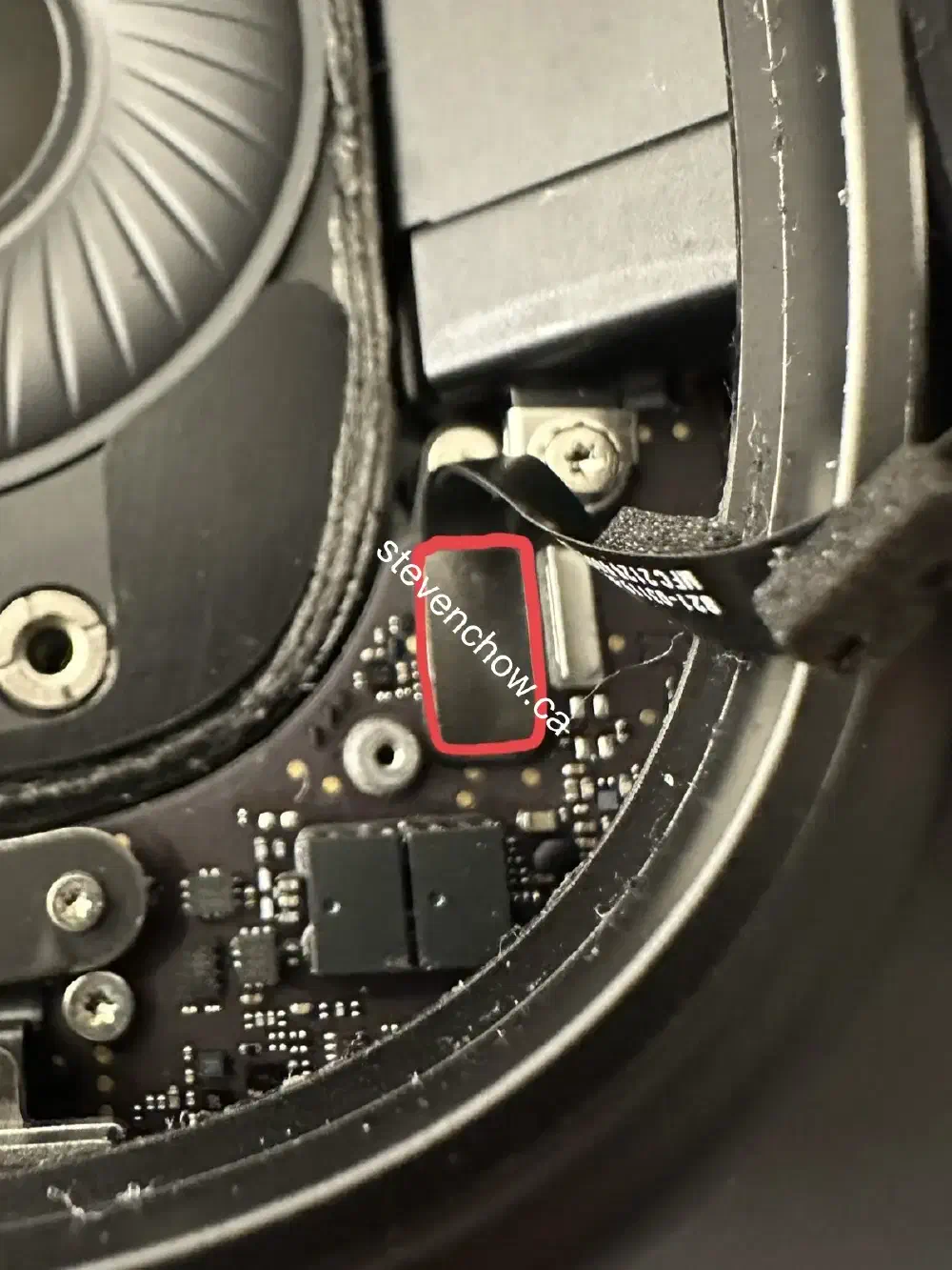
- constant swivelling can damage the thin ribbon connector that connects the board to the headband
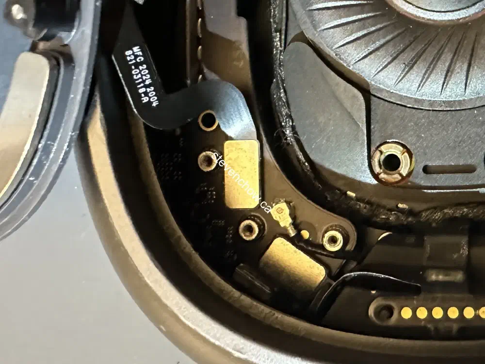
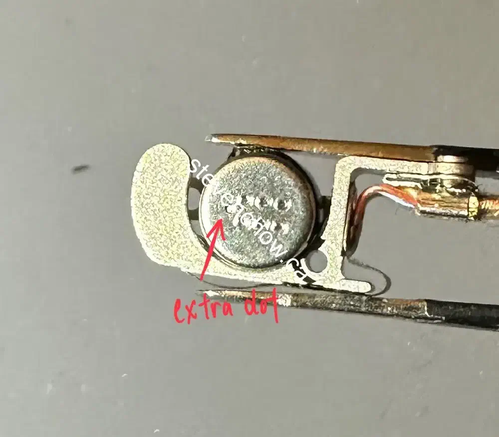
- moisture can cause corrosion on the pins and headband pins
To metigate the issues, it is possible to reinforce the ribbon with tape. For combatting the corrosion, a small amount of diaelectric grease can be used for protection.
##
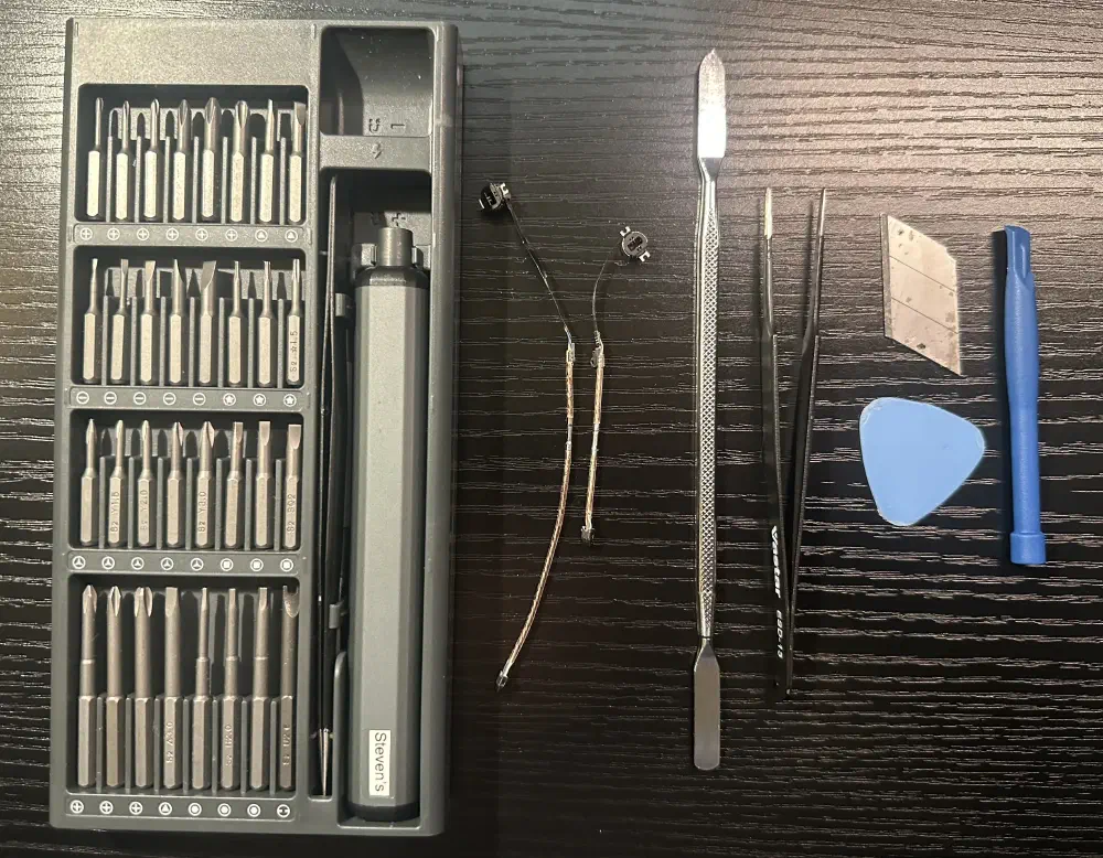
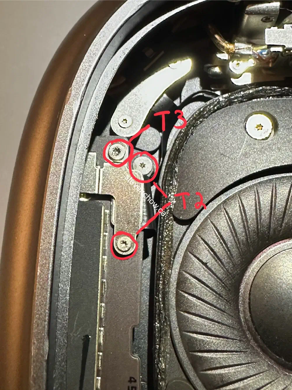
Tools required
#
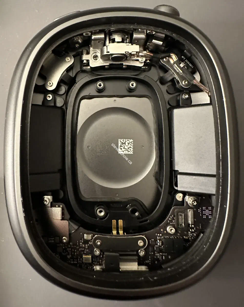
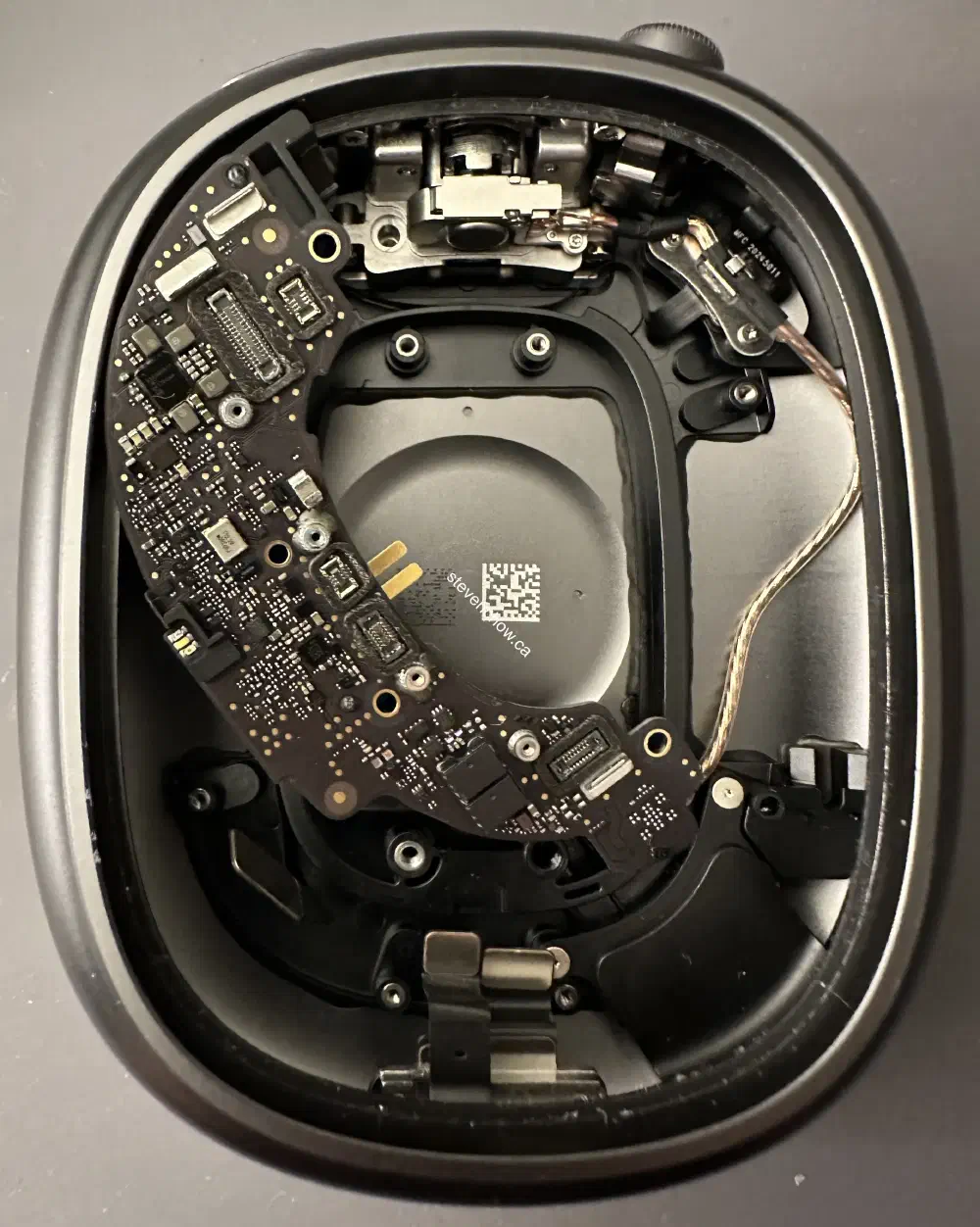
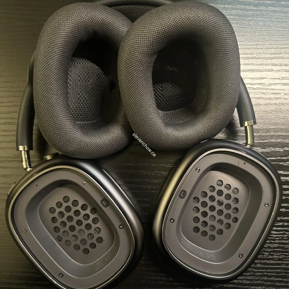
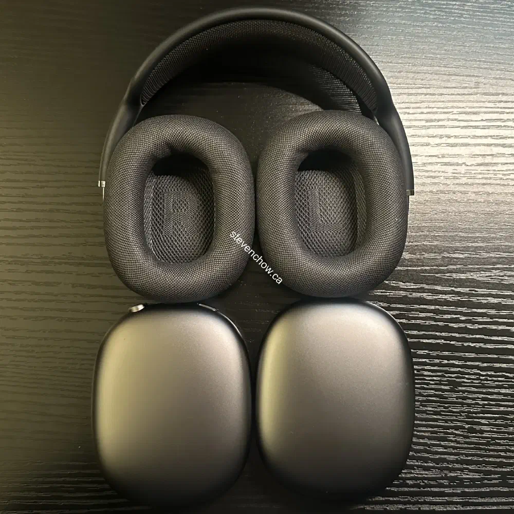
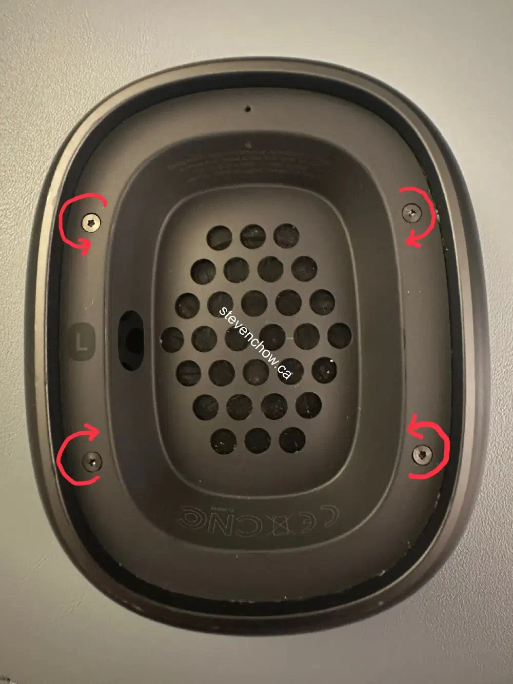
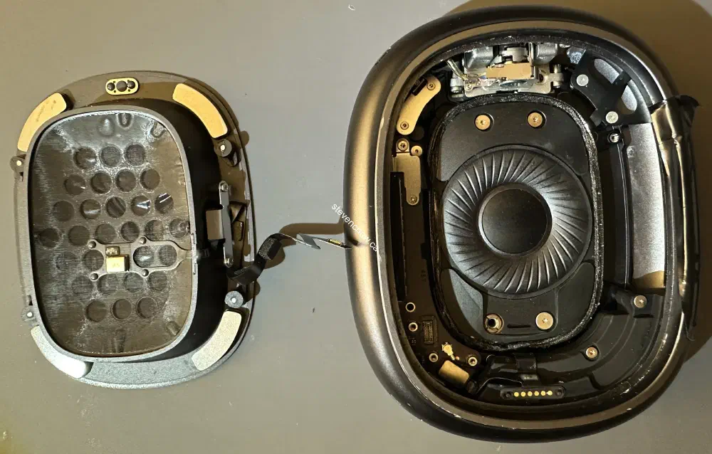
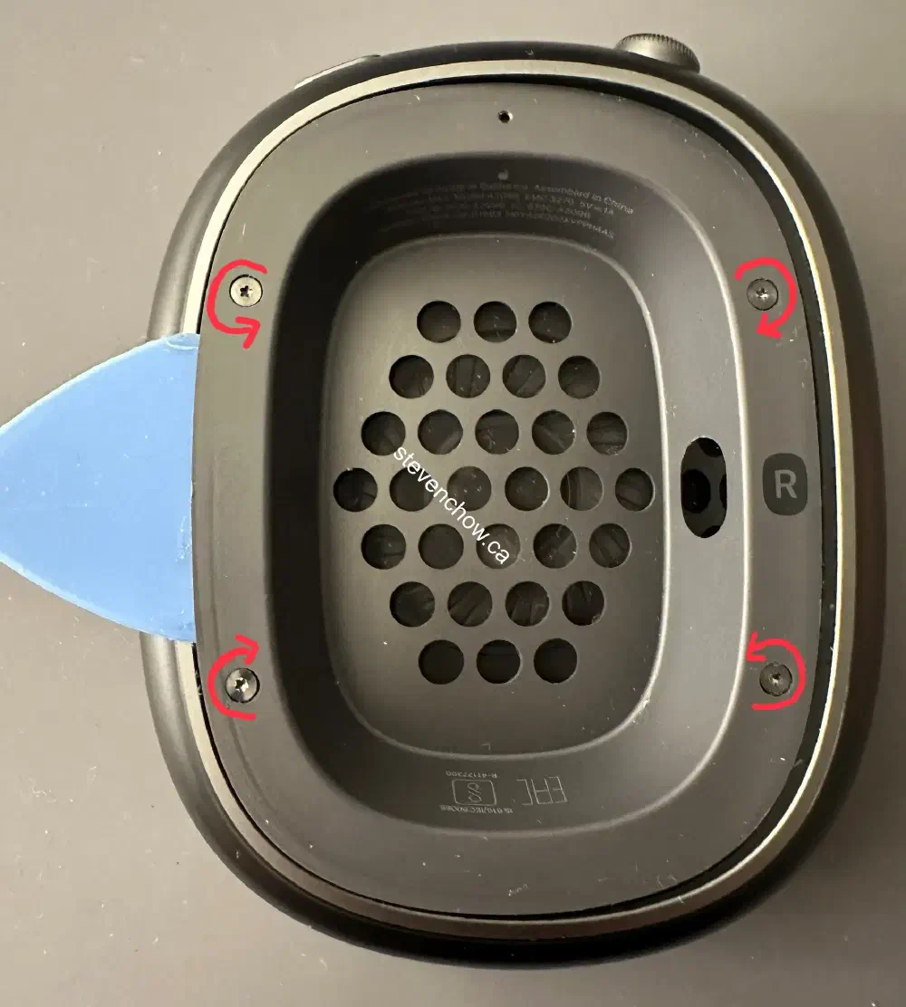
Remove earcups from Headband
#
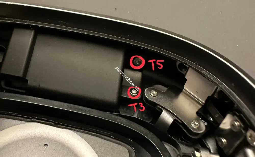
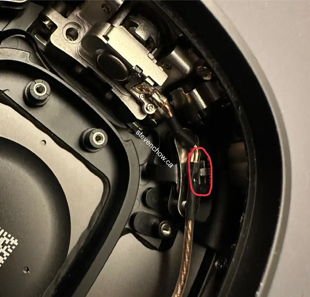
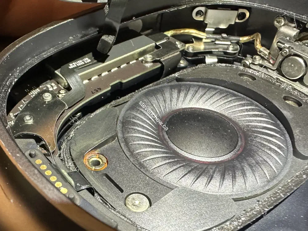
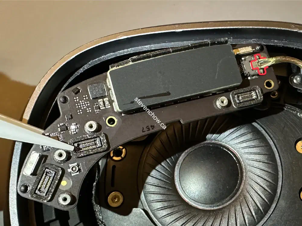
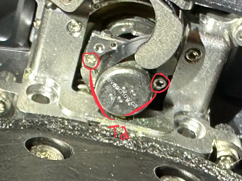
Left headband connector replacement
This side is a bit easier to repair since there’s no battery and the speaker does not need to be taken out.
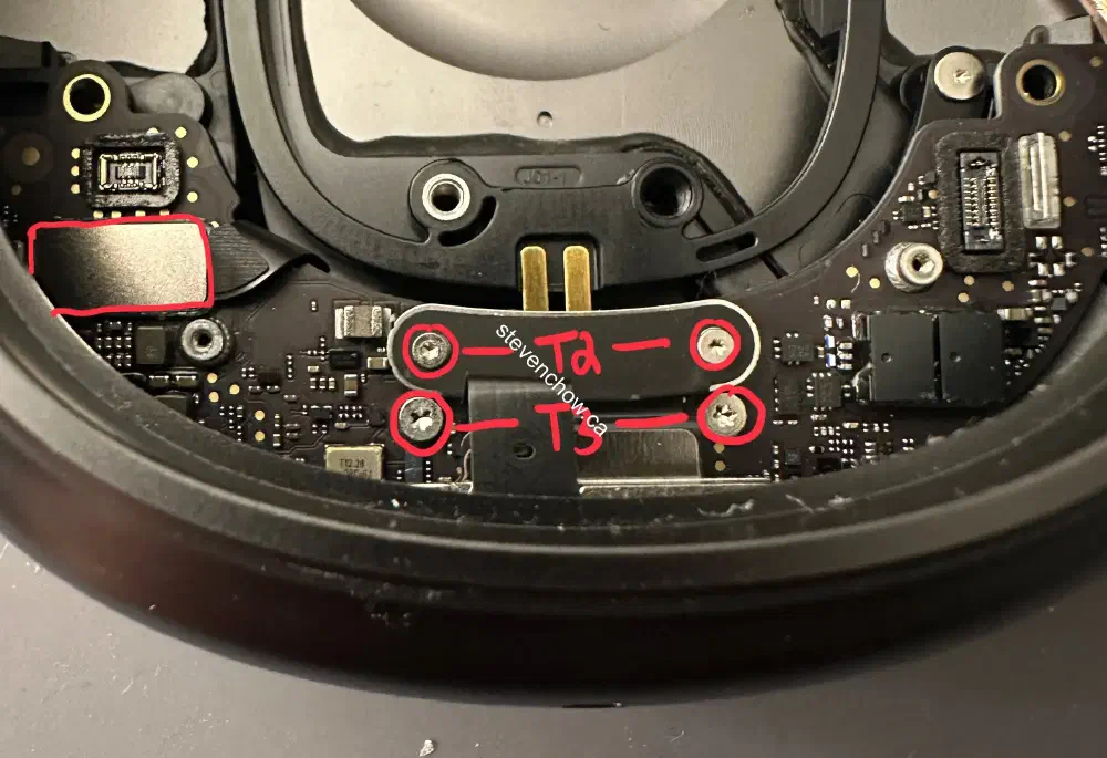
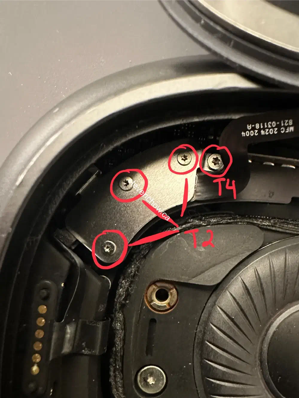
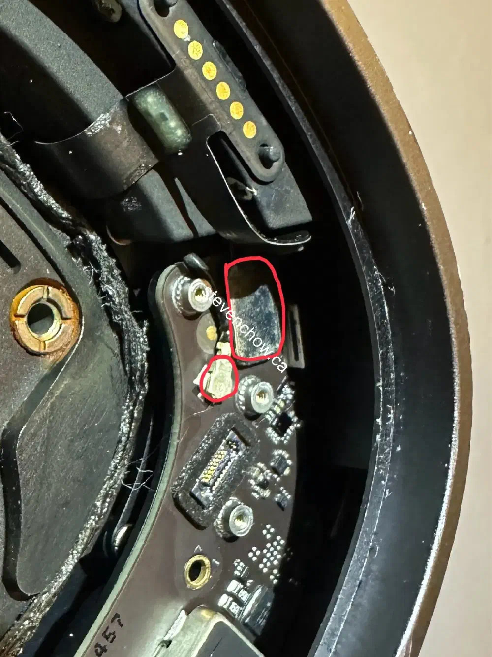
This is the hardest step. Apply heat or isopropyl alcohol to weaken adhesive and pry up on the side with the orientation label.
#
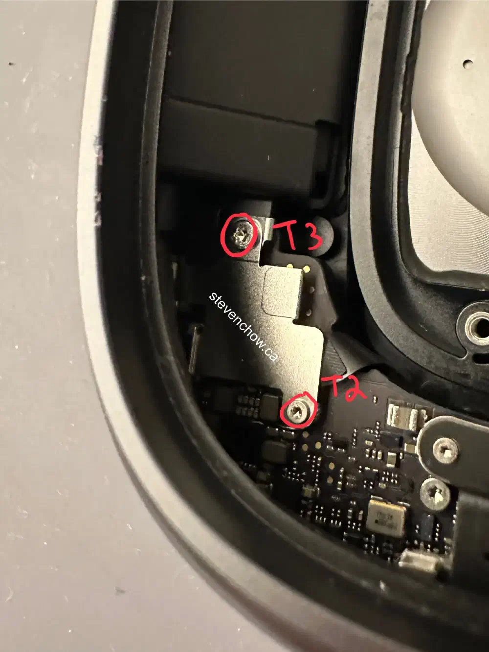
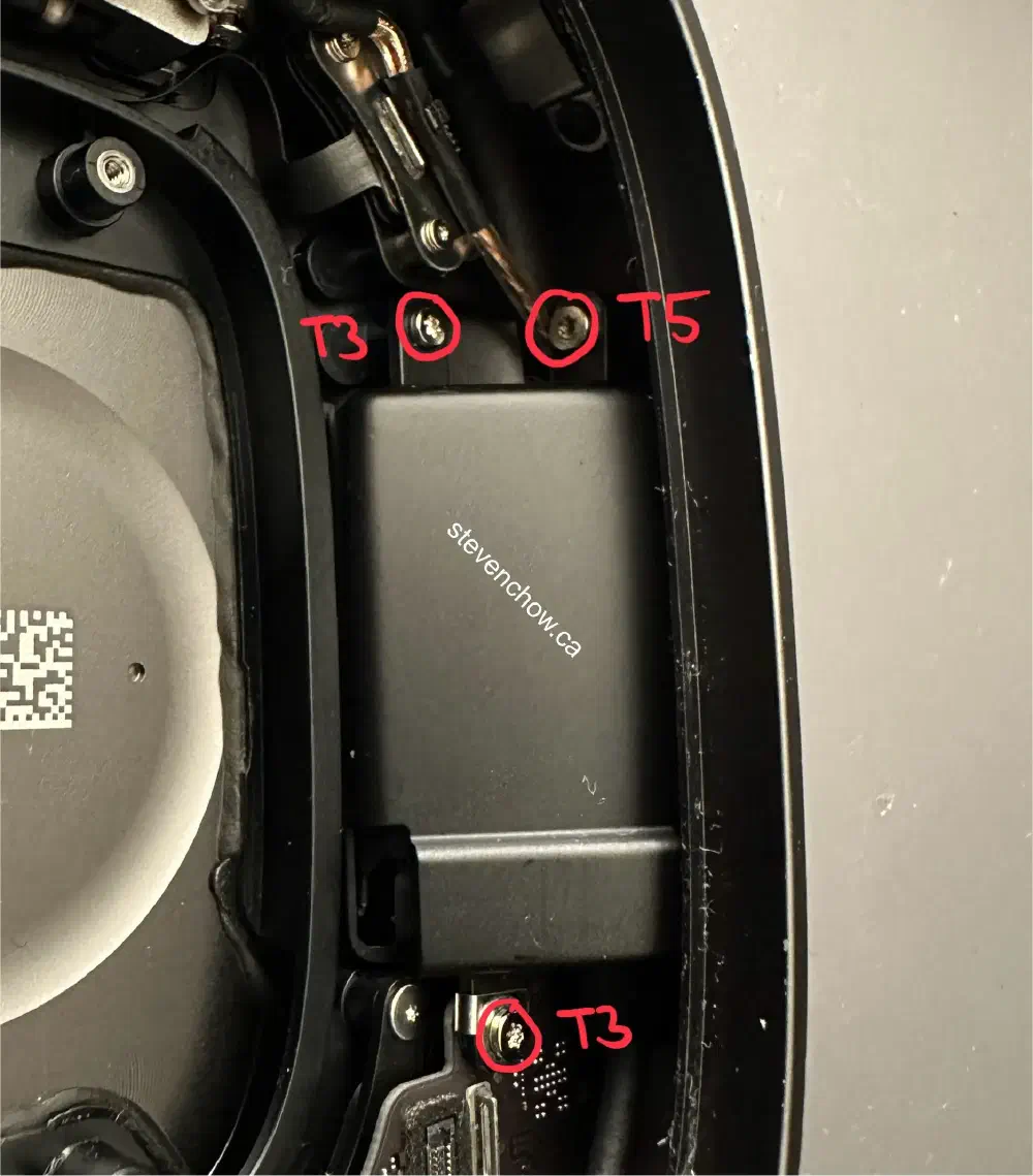
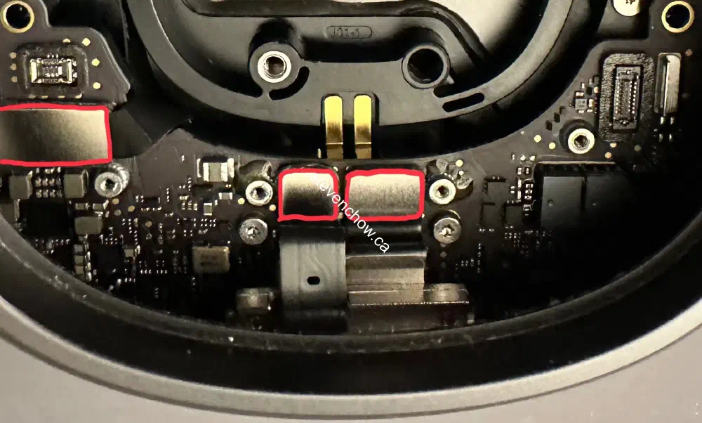
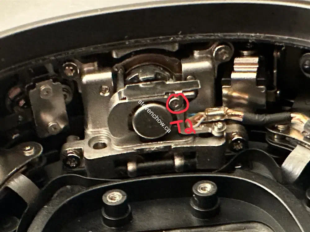
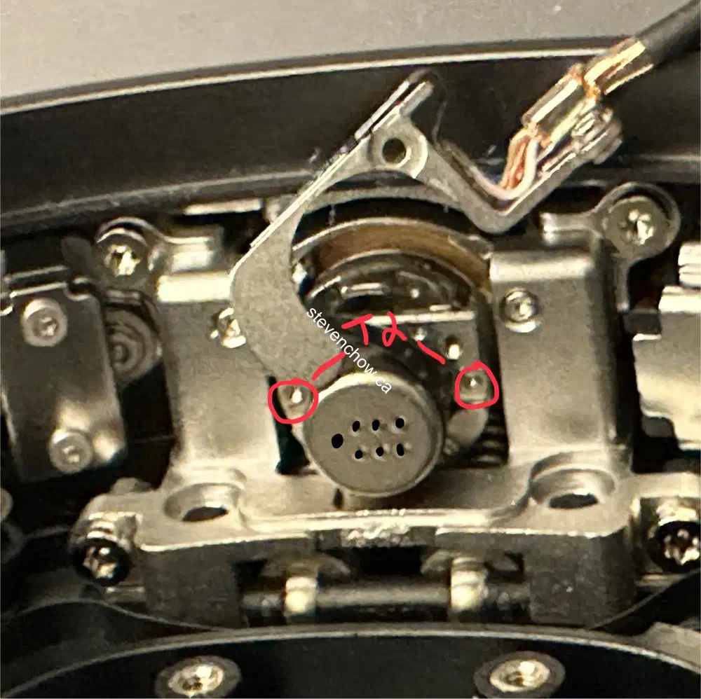
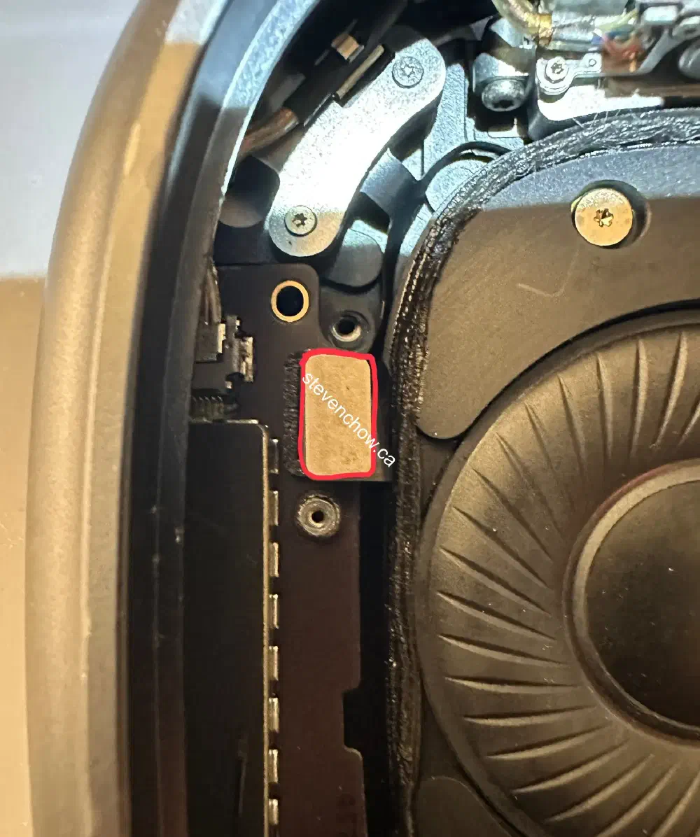
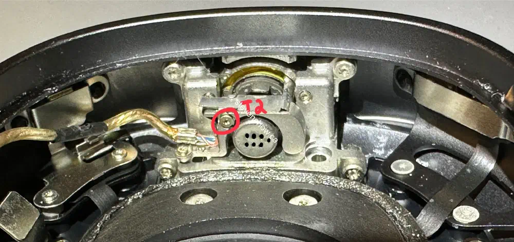
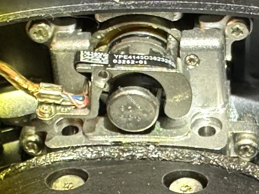
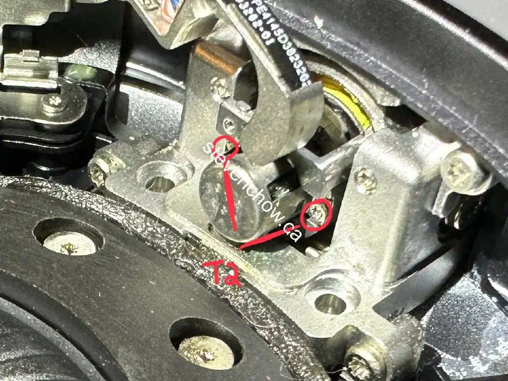
Right headband connector replacement
This is the hardest step. Apply heat or isopropyl alcohol to weaken adhesive and pry up on the side with the orientation label.
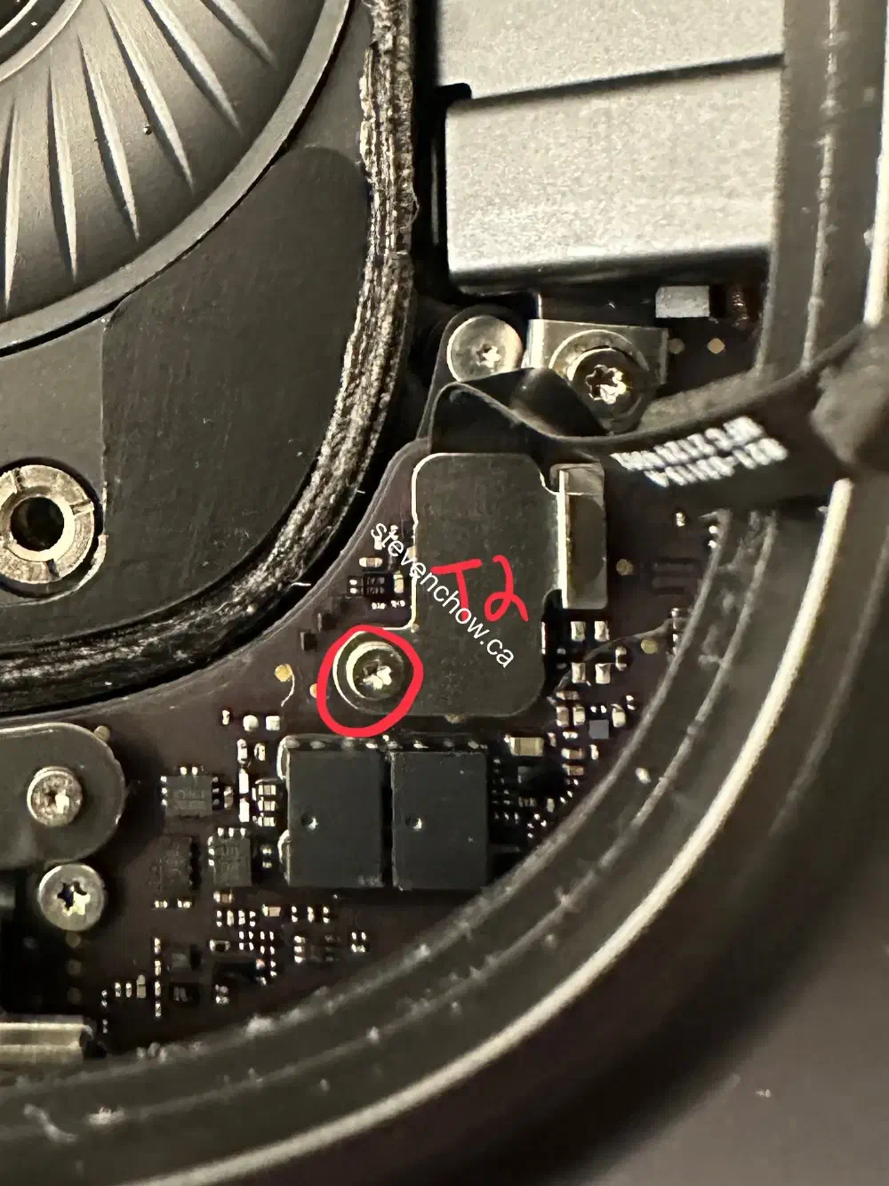
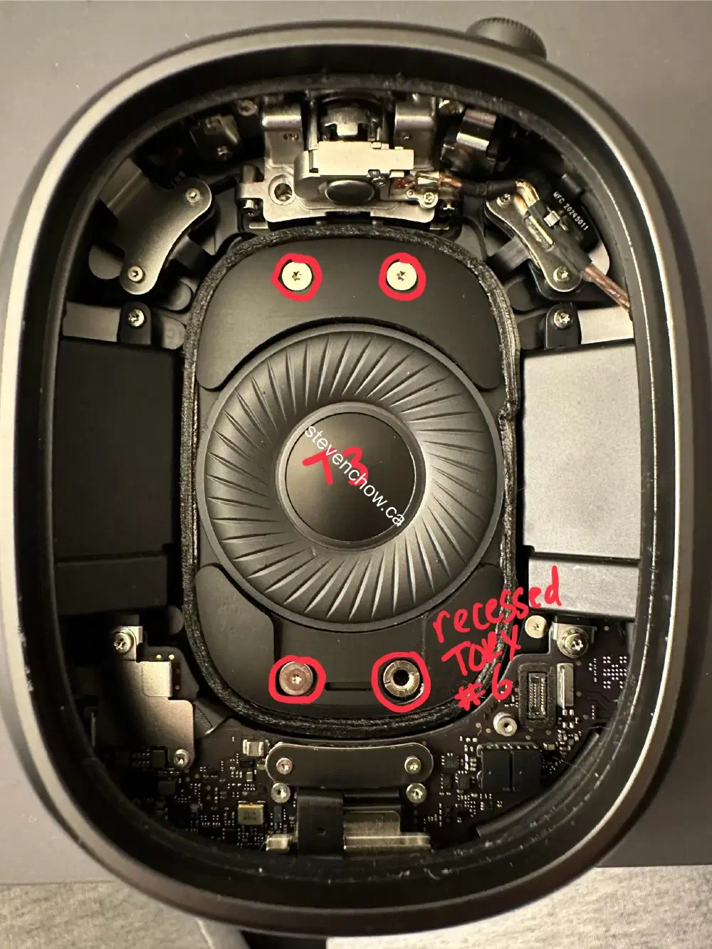
A flat pry tool can be used instead of a recessed torx #6 bit.